3D coaxial BHE
Problem description
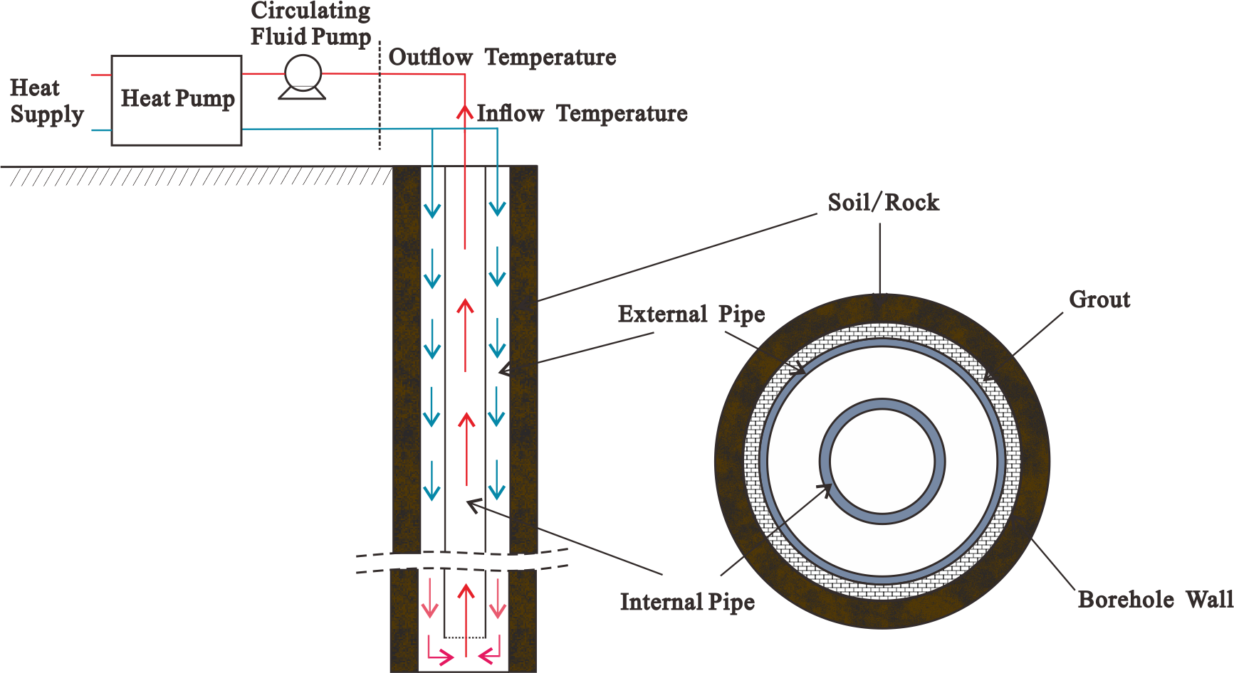
In recent years, Borehole Heat Exchangers (BHE) are very widely utilized to extract geothermal energy for building heating. For coaxial type of BHEs, an inner pipe is installed inside of an outer pipe, allowing the downward and upward flow to be separated. In some projects, very long coaxial BHEs are installed down to a 2-km depth, in order to extract more energy from the deep subsurface (Kong et al., 2017). Based on the flow directions, there are two types of coaxial BHEs. When downward flow is located in the inner pipe, it is called Coaxial-Centred (CXC) type. On the contrary, if the inflow is introduced in the annular space, it is called a CXA type. Detailed schematization of the CXA-type BHE system is shown in Figure 1. In this benchmark, the numerical model in OGS-6 has been tested for the 2 coaxial types of BHEs. The simulation results are compared with previous OGS-5 results and also the analytical solution proposed by Beier et al. (2014).

Coaxial BHE of CXA (Kong et al. (2017))
Model Setup
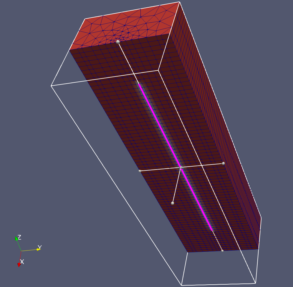
The implemented numerical model was established based on the dual continuum approach (Diersch et al. (2011)). The BHE is represented by the line elements co-located in the 3D mesh composed mainly by prisms. There are 3 primary variables on the line elements, namely 1) the inflow temperature 2) the outflow temperature and 3) the grout temperature. The geometry of the model is visualized in Figure 2. The length of the whole domain is 70 m with a square cross section of 20 m by 20 m. The mesh was intentionally extended in the horizontal direction, so that the impact of boundary conditions on the soil temperature distribution can be avoided even for the long-term simulation. The top of the DBHE is situated 10 m below the ground surface, with a total length of 50 m. Detailed parameters for the model configuration can be found in the following table.
| Parameter | Symbol | Value | Unit |
|---|---|---|---|
| Soil thermal conductivity | $\lambda_{s}$ | 2.5 | $\mathrm{W m^{-1} K^{-1}}$ |
| Soil heat capacity | $(\rho c)_{s}$ | $2.4\times10^{6}$ | $\mathrm{Jm^{-3}K^{-1}}$ |
| Length of the BHE | $L$ | 50 | $\mathrm{m}$ |
| Diameter of the BHE | $D$ | 0.216 | $\mathrm{m}$ |
| Diameter of the outer inflow pipe | $d_o$ | 0.16626 | $\mathrm{m}$ |
| Wall thickness of the outer inflow pipe | $b_o$ | 0.00587 | $\mathrm{m}$ |
| Wall thermal conductivity of the outer inflow pipe | $\lambda_{o}$ | 1.3 | $\mathrm{m}$ |
| Diameter of the inner outflow pipe | $d_i$ | 0.09532 | $\mathrm{m}$ |
| Wall thickness of the inner outflow pipe | $b_i$ | 0.00734 | $\mathrm{m}$ |
| Wall thermal conductivity of the inner outflow pipe | $\lambda_{i}$ | 1.3 | $\mathrm{m}$ |
| Grout thermal conductivity | $\lambda_{g}$ | 0.73 | $\mathrm{W m^{-1} K^{-1}}$ |
| Grout heat capacity | $(\rho c)_{g}$ | $3.8\times10^{6}$ | $\mathrm{Jm^{-3}K^{-1}}$ |

Geometry and mesh of the coaxial BHE model
The boundary condition of a BHE is always imposed from the aspect of inflow temperature (Hein et al., 2016). At every time step, the initial inflow temperature was calculated according to the heat load on the BHE, previous outflow temperature and parameters of circulating fluid, which can be described by:
$$ \begin{equation} P = \rho^r c^r Q^r(T_i - T_o), \end{equation} $$where $\rho^r c^r$ is heat capacity of circulating fluid and $Q^r$ is circulating fluid’s flow rate.
Results
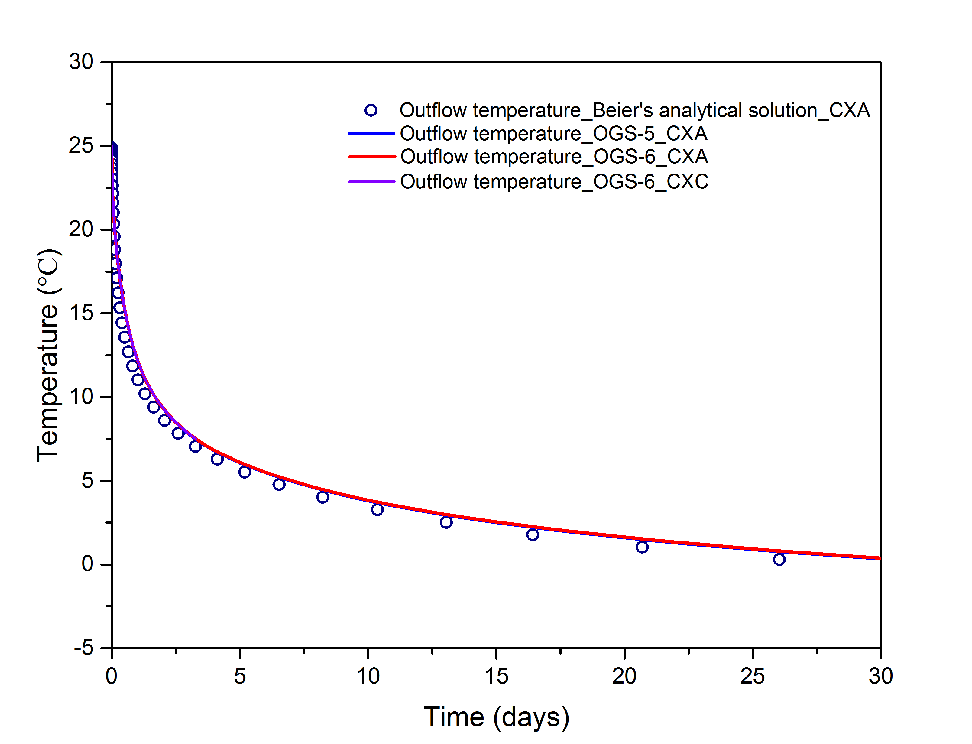
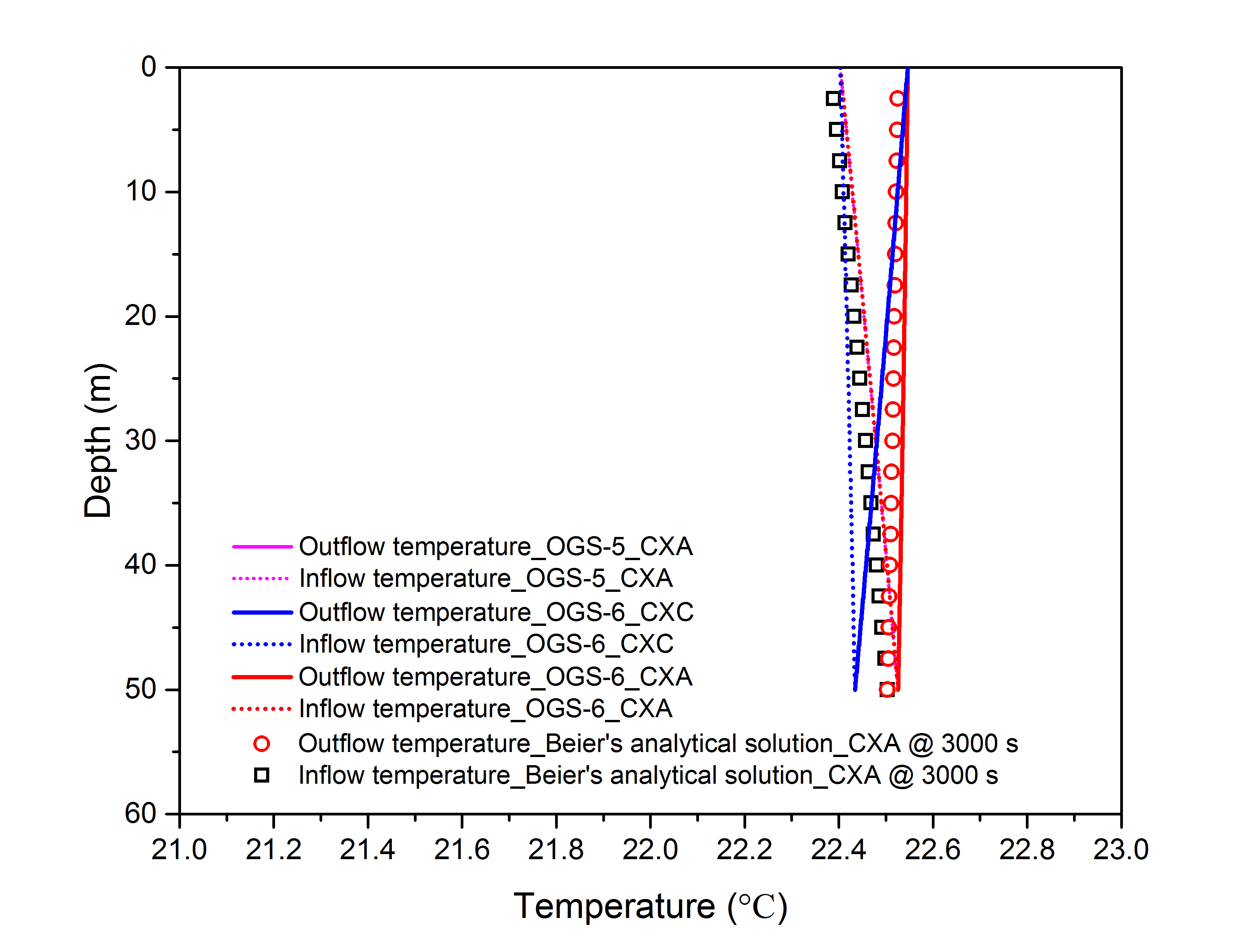
In Figure 3, the numerically simulated outflow temperature from OGS-6 was compared against the OGS-5 result, as well as the analytical solution by Beier et al. (2014). Also, the temperature distribution of circulating water inside of the BHE after 3000 seconds was presented in Figure 4. The comparison demonstrates that the numerical results and analytical solution can match very well and the biggest absolute error of outflow temperature is around 1.6 $^{\circ}$C at the starting up stage, while such error will decrease to around 0.5 $^{\circ}$C after 30 days’ operation. The maximum relative error regarding temperature distribution of circulating water after operation for 3000 s is around 2 %. The soil temperature verification can be seen in the Benchmark of 3D Beier sandbox.

Comparison with analytical solution and OGS-5 results

Distributed temperature of circulating water
Discussion
In the figures of results’ comparison, the numerical results cannot perfectly match Beier’s analytical solution. In fact, there are different kinds of analytical solution regarding the BHE process (Li et al., 2015). Here in this benchmark, Beier’s analytical solution was applied to compare with numerical results because it is a transient heat transfer model instead of the mean temperature approximation in the borehole. However, the inner pipe and outer pipe are both extracting energy from the soil in Beier’s analytical solution, which is slightly different from the numerical governing equations of the coaxial BHE and its physical process. Thus, the heat transfer coefficients among every part in analytical solution are different from numerical model except the thermal resistance between inner pipe and annulus. Besides, it was also offsetted while matching the measured temperature. At the same time, the numerical method applied in the OGS was firstly proposed by Diersch et al. (2011) and adapted in the commercial software afterwards. According to the comparison results, it can be proved that the numerical model was implemented successfully.
References
[1] Yan-Long, K., Chao-Fan, C., Hai-Bing, S., Zhong-He, P., Liang-Pings, X., & Ji-Yang, W. (2017). Principle and capacity quantification of deep-borehole heat exchangers. CHINESE JOURNAL OF GEOPHYSICS-CHINESE EDITION, 60(12), 4741-4752.
[2] Beier, R. A., Acuña, J., Mogensen, P., & Palm, B. (2014). Transient heat transfer in a coaxial borehole heat exchanger. Geothermics, 51, 470-482.
[3] Diersch, H. J., Bauer, D., Heidemann, W., Rühaak, W., & Schätzl, P. (2011). Finite element modeling of borehole heat exchanger systems: Part 1. Fundamentals. Computers & Geosciences, 37(8), 1122-1135.
[4] Hein, P., Kolditz, O., Görke, U. J., Bucher, A., & Shao, H. (2016). A numerical study on the sustainability and efficiency of borehole heat exchanger coupled ground source heat pump systems. Applied Thermal Engineering, 100, 421-433.
[5] Li, M., & Lai, A. C. (2015). Review of analytical models for heat transfer by vertical ground heat exchangers (GHEs): A perspective of time and space scales. Applied Energy, 151, 178-191.
This article was written by Chaofan Chen, Haibing Shao. If you are missing something or you find an error please let us know.
Generated with Hugo 0.122.0
in CI job 545140
|
Last revision: February 26, 2025
Commit: [PCS] Avoid to compute the analytic block in ed9789e
| Edit this page on